Tunnel Ventilation Overview
Tunnels play a variety of roles in our daily lives, not only for roads and railroads, but also other familiar purposes. More new ideas are coming up.
There are two types of ventilation for underground tunnels: ventilation required during tunnel construction (temporary) and ventilation for tunnel operation (permanent).
TEMPORARY VENTILATION FOR TUNNEL
The tunnel construction works are mainly carried out by drill and blast method, which have many safety and health issues due to the emission of dust and many poisonous gasses. Hence it is essential to provide external fresh air required to allow a safe environment for workers working inside the tunnel.

PERMANENT VENTILATION FOR TUNNEL
The need for tunnel ventilation is critical for the life and safety of any person utilizing the tunnels. Typically, the ventilation fans are used to dilute toxic and inflammable gases to a safe level; dust and smoke dispersed; excessive heat should be relieved; and escape routes must be kept clear from smoke.
There are three basic types of control that can be utilized: portal to portal, shaft to shaft, and portal to shaft. These are used independently or in conjunction with each other. Fans utilized are both axial, reversible and unidirectional.

WHY WE ARE DIFFERENT
FALVENT is a Saudi manufacture offers a complete solution to meet underground ventilation needs during construction and after operation to achieve the air quality and provide standard ventilation.
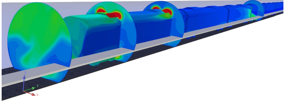
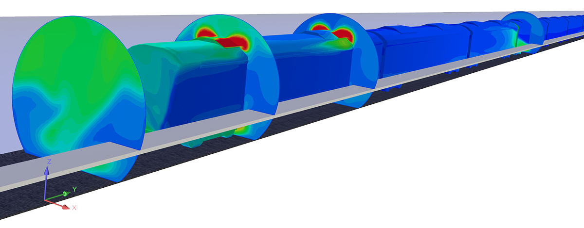
FALVENT work with a qualified consultants to delivery of projects on time, to an agreed cost and to the highest quality. In order to optimize our solutions, we also use advanced CFD analysis to get an effective performance.
FALVENT cooperates with the strategic cooperation with main advantage manufactories European and Chinese manufacturers specialized in tunnel ventilation to produce fans according to international manufacturing as well as in line with the Saudi market.
FALVENT starts working with its customers from the initial study of the tunnel, in order to provide an optimal solution for each project. Also, FALVENT has a technical assistance department with the following services:
- Installation and Erection.
- Testing and Commissioning
- Maintenance and Diagnostics
- Spare parts and Upgrade.

JET FANS AND LARAG AXIAL FLOW FANS
The jet fans and large flow axial fans can be used to clear the atmosphere inside the tunnel and achieve the safe evacuation during the emergency case.
TUNNEL JET FANS (CFC SERIES)
- Casing made of Carbon steel with epoxy paint protective coating. and provided with an adjustable bench that allows a wide range of motors to be installed.
- 50 mm thick and minimum length of 100 mm silencer made with 70kg/m3 density rockwool and manufactured using perforated plate inside.
- The silencers are placed on both sides of the fan casing.
- and fitted with inlet and outlet cones designed for minimum pressure loss
- Protection guard for inlet and deflector in the outlet.
- Junction box on the casing for easy on-site wiring.
- Mounting support included.
- Impeller made of aluminum alloy with size 500 mm to 1600 mm
- Trust ranges which vary from 185 N up to 2810 N. Unidirectional or Reversible blade


- TEFC Three phase motor, 380V/60Hz.
- Degree of protection IP 55.
- Calss of insulation F.
- Efficient IEC standard motor, efficiency class IE2 or IE3
- Specific bearings for operating between 20,000 h and 100,000 hours.
| Fan type | Thrust Motor | rating | Volume | flow Air speed Rotor | RPM | Sound power |
|---|---|---|---|---|---|---|
| [N] | [kW] | [m3/s] | [m/s] | [RPM] | [dB(A)] | |
| CFC 500 | 109 | 2.2 | 4.39 | 22.2 | 2900 | 87 |
| CFC 630 | 290 382 470 542 |
7.5 12 15 18.5 |
8.91 10.23 11.34 12.18 |
28.58 32.81 36.36 39.06 |
2900 2900 2940 2940 |
90 92 93 94 |
| CFC 710 | 388 492 573 663 |
12 15 18.5 26 |
11.59 13.06 14.09 15.15 |
29.28 32.98 35.59 38.28 |
2900 2940 2940 2940 |
99 101 102 105 |
| CFC 800 | 625 740 |
18.5 26 |
16.58 18.04 |
32.98 35.89 |
2940 | 105 107 |
| CFC 900 | 343 417 525 |
7.5 10 15 |
14.14 15.59 17.49 |
22.23 24.5 27.5 |
1450 1470 1470 |
92 93 95 |
| CFC 1000 | 507 615 695 749 |
11 15 18.5 22 |
19.1 21.04 22.36 23.22 |
24.33 26.79 28.48 29.57 |
1470 1470 1470 1470 |
95 96 97 98 |
| CFC 1120 | 713 805 869 1004 |
15 18.5 22 30 |
25.38 26.98 28.01 30.11 |
25.76 27.37 28.43 30.56 |
1470 1470 1470 1470 |
97 97 98 100 |
| CFC 1250 | 1030 1198 1731 |
22 30 75 |
34.04 36.71 44.13 |
27.74 29.91 35.96 |
1470 1470 1470 |
100 101 103 |
| CFC 1600 | 1105 1381 1543 2236 2438 |
22 30 37 75 90 |
39.68 44.37 46.9 56.45 58.94 |
25.78 28.82 30.47 36.67 38.29 |
1470 1470 1470 1470 1470 |
99 101 101 04 105 |
| CFC 1400 | 2052 2653 2870 |
55 75 90 |
61.81 70.28 73.1 |
30.74 34.95 36.36 |
1470 1470 1470 |
105 106 106 |
For reversible jet fans will give approximately 5% lower thrust than those shown in the table.
Systems using Novenco tunnel fans employ the jet prin- ciple to push air through the tunnel from intake to ex- haust. The air is moved by impulses injected by a suf- ficient number of tunnel fans mounted in the ceiling.
Tunnel fans function by sucking a small part of air in and expelling it with high speed. The ambient air is thereby set in motion.
LARAG AXIAL FLOW FANS (AXF SERIES)
- Blades and hub are made of cast aluminum, dynamically balanced
- Aerofoil impeller with adjustable pitch angel
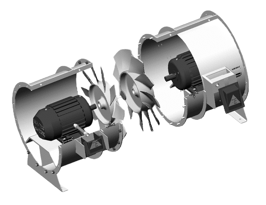
- Double-stage (impellers) axial fan in counter-rotating design (i.e. spin in opposite directions).
- Unidirectional or Reversible blade.
- Installation in a horizontal and vertical position
- Connection flange and mounting feet.
- Efficient IEC standard motor, efficiency class IE2 or IE3, frequency controllable.
- Degree of protection IP 55, insulation class F.
- Terminal box mounted at the outside of casing for easy wiring.
- Mounting support included.
- Sizes up to 3000 mm diameter


- Apply to smoke, fire and other hot sources with working temperature 300°C or 400°C/ 120 min
- Painting in a color other than the standard.
- Galvanized steel sheet housing.
- Housing made of stainless steel.
- Housing made of acid-proof steel.
- Motor for other than standard voltage and power frequency.
- Engine with a different degree of protection.
- Motor with a different insulation class.
| Model | Diameter | Max Air Flow | Max Pressure | Motor Speed | Voltage/Frequency | Power | Article Number |
|---|---|---|---|---|---|---|---|
| mm | m3/hr | Pa | rpm | V/Hz | KW | ||
| AXF 800 D4 T01 | 800 | 710 | 1600 | 1480 | 380 V|60 HZ | 2X7.5 | 2234401 |
| AXF 800 D4 T02 | 800 | 820 | 2240 | 1480 | 380 V|60 HZ | 2X11 | 2234402 |
| AXF 900 D4 T01 | 900 | 927 | 1834 | 1480 | 380 V|60 HZ | 2X15 | 2234403 |
| AXF 900 D4 T02l | 900 | 1090 | 2830 | 1480 | 380 V|60 HZ | 2X22 | 2234404 |
| AXF 900 D4 T03 | 900 | 1325 | 3200 | 1480 | 380 V|60 HZ | 2X30 | 2234405 |
| AXF 1000 D4 T01 | 1000 | 1500 | 3500 | 1480 | 380 V|60 HZ | 2X37 | 2234406 |
| AXF 1000 D4 T02 | 1000 | 1736 | 3859 | 1480 | 380 V|60 HZ | 2X45 | 2234407 |
| AXF 1120 D4 T01 | 1120 | 1985 | 4150 | 1480 | 380 V|60 HZ | 2X55 | 2234408 |
| AXF 1120 D4 T02 | 1120 | 2281 | 4628 | 1480 | 380 V|60 HZ | 2X75 | 2234409 |
| AXF 1250 D4 T01 | 1250 | 2912 | 5355 | 1480 | 380 V|60 HZ | 2X110 | 2234410 |
| AXF 1250 D4 T02 | 1250 | 3300 | 5920 | 1480 | 380 V|60 HZ | 2X132 | 2234411 |
| AXF 1400 D4 T01 | 1400 | 4116 | 6860 | 1480 | 380 V|60 HZ | 2X160 | 2234412 |
| AXF 1400 D6 T01 | 1400 | 2725 | 3100 | 980 | 380 V|60 HZ | 2X75 | 2234413 |
| AXF 1500 D6 T01 | 1500 | 3352 | 3559 | 980 | 380 V|60 HZ | 2X90 | 2234414 |
| AXF 1600 D6 T01 | 1600 | 4068 | 4049 | 980 | 380 V|60 HZ | 2X110 | 2234415 |
| AXF 1700 D6 T01 | 1700 | 4879 | 4571 | 980 | 380 V|60 HZ | 2X160 | 2234416 |
| AXF 1800 D6 T01 | 1800 | 5792 | 5124 | 980 | 380 V|60 HZ | 2X200 | 2234417 |
| AXF 1900 D6 T01 | 1900 | 6175 | 5412 | 980 | 380 V|60 HZ | 2X220 | 2234418 |
| AXF 2000 D6 T01 | 2000 | 6684 | 5820 | 980 | 380 V|60 HZ | 2X250 | 2234419 |
| AXF 2200 D6 T01 | 2200 | 8020 | 6926 | 980 | 380 V|60 HZ | 2X315 | 2234420 |
| AXF 2400 D6 T01 | 2400 | 9550 | 8173 | 980 | 380 V|60 HZ | 2X355 | 2234421 |

When two axial fans rotating in the same direction are operated in series, the outlet fan further swirls the swirling wind from the inlet fan, generating a spreading flow of air.
However, a Counter Rotating Fan’s outlet fan rotating in the opposite direction weakens the swirling components of the wind from the inlet fan, generating a straight air flow and the noise is also reduced
Because of the difference in the air flow within the fan, a Counter Rotating Fan has a much higher static pressure than two axial fans rotating in the same direction in series.
The performance of the fan as two separate stages is much poorer than that of the two stages operating as a single integral unit and also the performance of the two stages give 2.7 times pressure development of a big single stage fan.
Also, these fans technology cannot be split into their two components and operated as two identical single-stage fans.
VFD ROLE IN TUNNEL VENTILATION
The variable frequency drive (VFD) controls the fan motor running achieve the effective control of the tunnel ventilation fans as follows:
01
The variable frequency drive (VFD) controls the fan motor running achieve the effective control of the tunnel ventilation fans as follows:
01
The variable frequency drive (VFD) controls the fan motor running achieve the effective control of the tunnel ventilation fans as follows:
02
Has a very significant impact on energy consumption. Very small speed changes can yield large energy savings – a speed reduction of 10% results in a 27% energy saving.
02
Has a very significant impact on energy consumption. Very small speed changes can yield large energy savings – a speed reduction of 10% results in a 27% energy saving.
03
Reducing fan speeds can also reduce noise levels – reducing the speed by only 20% will reduce sound pressure by more than 50%.
03
Reducing fan speeds can also reduce noise levels – reducing the speed by only 20% will reduce sound pressure by more than 50%.
04
Helps in evacuation and fire suppression promptly changing fan speed and rotation direction according to a need.
04
Helps in evacuation and fire suppression promptly changing fan speed and rotation direction according to a need.

TUNNEL VENTILATION SYSTEMS
Ventilation systems may be configured based on different key elements such as the type of tunnel, length, slope or traffic volume:

Longitudinal Ventilation

Transverse Ventilation

Semi-transverse Ventilation
CFD APPLICATIONS IN TUNNEL VENTILATION ANALYSIS
Falvent use the CFD simulations for predicting ventilation effectiveness inside underground tunnels. CFD analysis can help to simulate various design configurations and situations thereby verifying the performance of the installed systems virtually and the using CFD modelling to rapidly provide with accurate simulation results for various design scenarios as well as CFD allows to cut significant costs on testing and faster project delivery.

